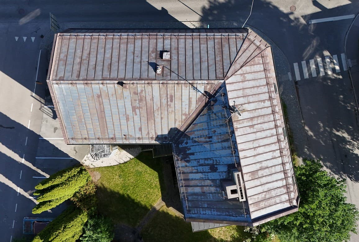
Solar PV installation · In-depth inspection
In-depth inspection that distinguishes defects from thermal indications
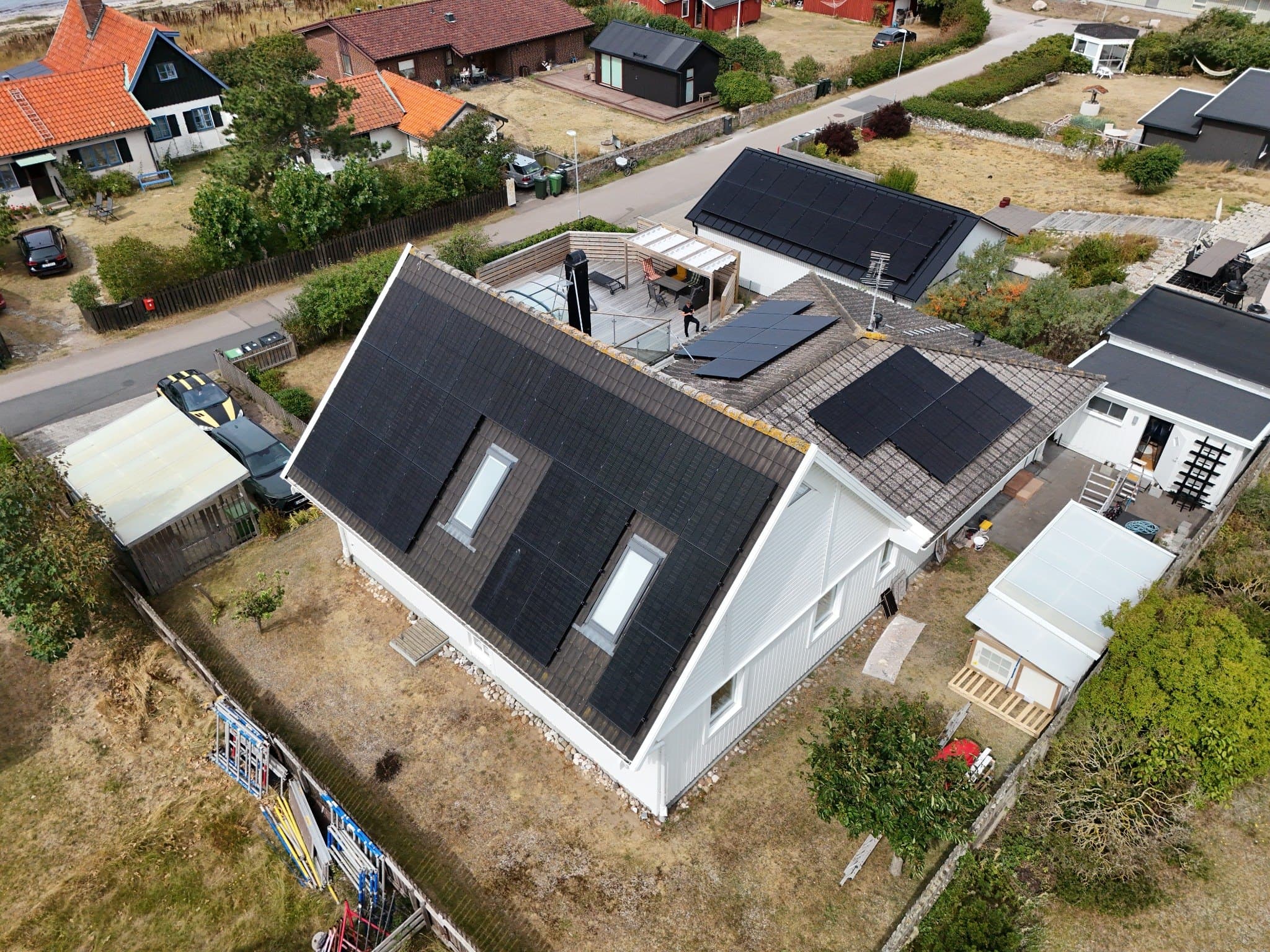
A comprehensive review of 40 modules across three roof orientations. RGB, thermal imaging, mounting, electrical components and operating data were analysed together to provide a balanced, actionable assessment.
- RGB + radiometric thermal imaging
- 40 modules
- Operational and installation inspection
- 40
- modules reviewed
- Across three roof orientations
- 69
- images in the report
- Details, RGB, IR and paired images
- 11,0
- kW documented output
- Grid-connected with no alarm displayed
- 8
- inspection areas
- From panels to documentation
- 01
The requirements
The client needed to verify both the installation's operation and its condition. Production data alone could not show whether a thermal spot was a genuine module defect or a low-priority indication.
- 02
The execution
All modules were reviewed using RGB and IR material. Thermal patterns were compared across multiple modules and against corresponding visual images, while mounting, cabling, the inverter, switches and operating status were also checked.
- 03
The deliverables
A 12-page inspection report with checklists, a system overview, 69 documented images, a detailed thermal assessment and a prioritised list of technical follow-up actions.
Summary assessment
Normal operation — clear installation issues for follow-up
The installation returned to normal operation with no alarm displayed and produced approximately 11 kW. The main technical deviation was insufficient side clearance at the inverter. A faint thermal spot pattern was not assessed as a clear isolated hotspot, but a comparative check was recommended at the next IR inspection under stable conditions.
What the deliverables look like
A report designed for further use
Each observation moves from image to assessment and then to a prioritised action.
- 01Scope
- 02Method
- 03Observation
- 04Assessment
- 05Recommendation
- 06Priority
- 07Timeframe
UAS Inspect
12-page inspection report
- 01
Inspection checklist
Eight inspection areas with status and clear responsibility boundaries.
- 02
System overview
Panel count, orientations, mounting, components and operating status.
- 03
RGB + IR analysis
Paired images for more reliable thermal interpretation and location.
- 04
Prioritised follow-up
Deviations, verified functions and recommended next steps.
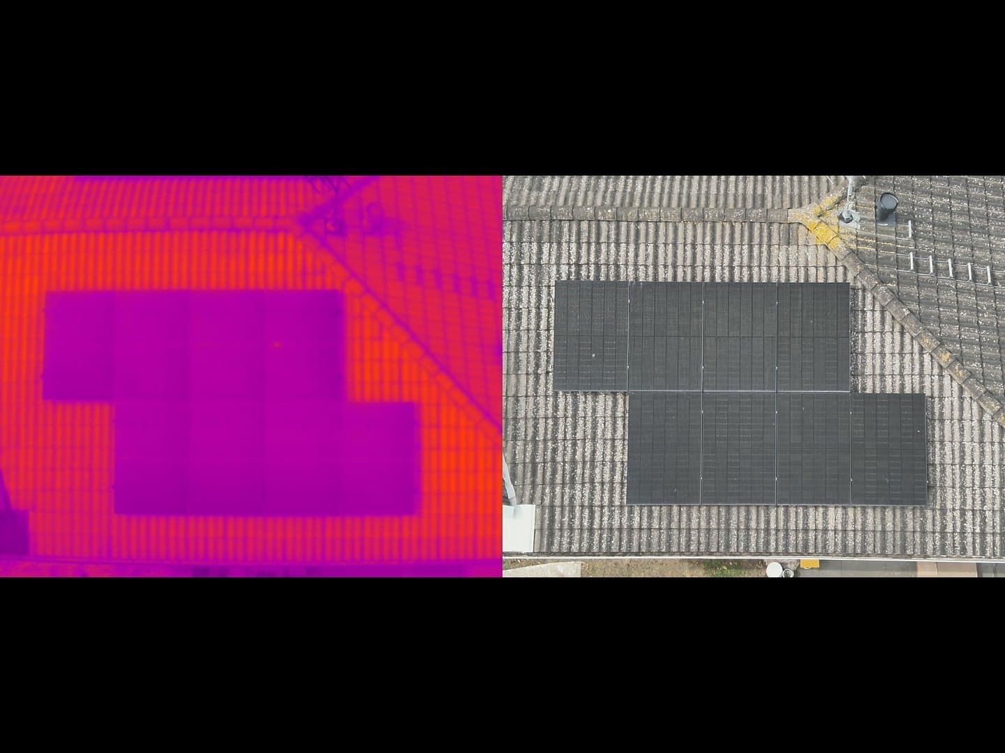
Images, references, status and next steps in one deliverable. The report structure above is visualised using the real project.
Selected observations
Findings you can understand and act on
A selection is shown below. The full report contains more inspection points and image references.
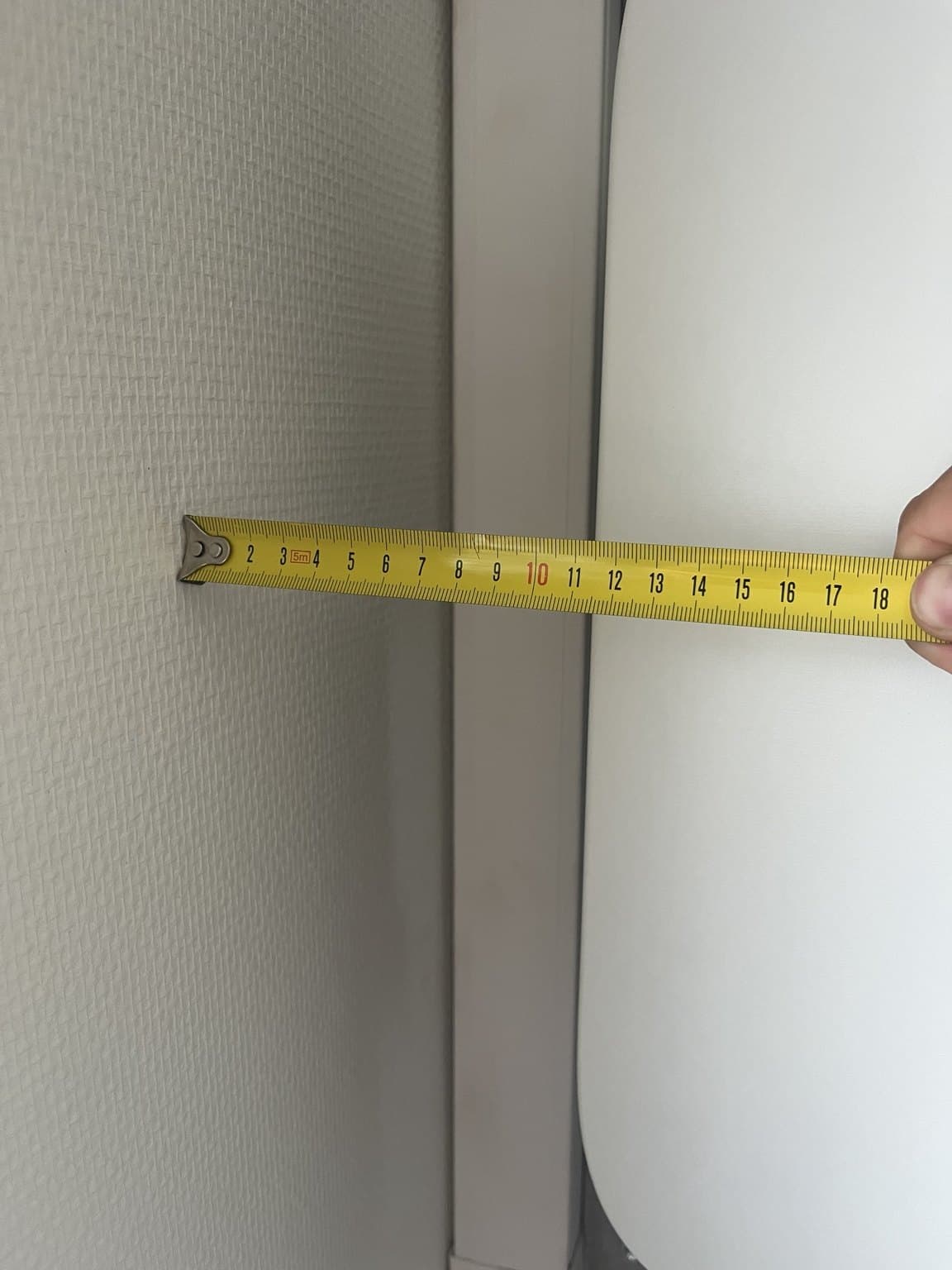
Side clearance below the manufacturer's requirement
- Observation
- The inverter's side clearance to the wall was measured at approximately 120 mm.
- Assessment
- The manufacturer specifies at least 350 mm. This leaves a clearance shortfall of approximately 230 mm.
- Recommendation
- Adjust the positioning or obtain written confirmation from the manufacturer regarding this installation.
Thermal spot pattern analysed in context
- Observation
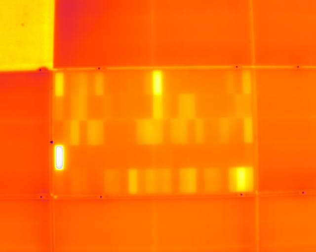
- One spot was more pronounced than the others, but fainter symmetrical spots were visible on several panels.
- Assessment
- RGB images showed no corresponding damage, dirt or shading. The pattern therefore did not support a clear isolated cell hotspot.
- Recommendation
- Follow up radiometrically at the next IR inspection under stable irradiance, and investigate further only if a clear temperature deviation is found.
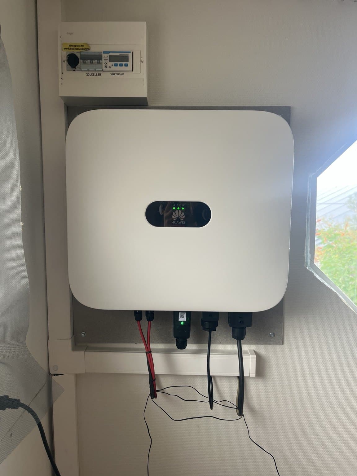
Inverter and restart documented
- Observation
- The inverter showed normal grid-connected operation. AC and DC switches were operated during the inspection.
- Assessment
- Shutdown and normal restart were confirmed with no alarm displayed. Instantaneous output was approximately 11.0 kW.
- Recommendation
- Keep the status as a reference and add commissioning and test records if they are missing.
From findings to a plan
Prioritised follow-up
The report conclusions are brought together so the responsible party can quickly see what should be done, why and when.
| Action | Beskrivning | Priority | Timeframe |
|---|---|---|---|
| Inverter | Correct the side clearance or obtain written verification. | Priority | As soon as possible |
| Thermal follow-up | Compare the spot pattern radiometrically under stable irradiance. | Follow up | Next IR inspection |
| Labelling | Apply durable labels to conductors and cables at the inverter. | Complete documentation | During servicing |
| Test documentation | Request and review commissioning and test records. | Complete documentation | Next follow-up |
What the client receives
A complete decision support package — not a folder of drone images.
The deliverables can be used for maintenance planning, service orders, procurement, warranty matters and discussions with property owners or end customers.
- 01Inspection checklist for the entire installation
- 02RGB and IR images from comparable angles
- 03Location and technical assessment of each indication
- 04Documented operating status and functional test
- 05Prioritised follow-up for servicing, warranties and customer discussions
More real projects
See the next decision support package